I don't quite follow - surely positive pressure is required to release spring brakes just as for diaphragm chambers?
I worked on a truck which was fitted with one standard diaphragm chamber and one spring brake chamber on each rear axle, both attached to the same actuating bar and operating from the same air system 'Tee'. There were no extra relays in that system.
I never looked too closely as it was being returned to standard but, although of dubious legality, it worked ok. There was a hand valve on the steering column to operate the brakes as a hand brake, although once any air had drained from the system only the spring brakes were holding it. The disc hand brake had been removed completely.
I would think the best and simplest conversion would be as per Sam's and replace the standard units with wind-off spring units.
- MG
M1 / M1A1 Heavy Wreckers and Accessories
Moderator: kw573
-
tootallmike

- G-Sergeant Major

- Posts: 152
- Joined: Thu Feb 08, 2007 5:27 am
- Location: South London, England
Re: M1 / M1A1 Heavy Wreckers and Accessories
Green Barn Services
Preservation, restoration, maintenance, repair & upgrade
Engine conversion specialists
WLF parts fs
Preservation, restoration, maintenance, repair & upgrade
Engine conversion specialists
WLF parts fs
-
40 Chevy

- G-First Lieutenant

- Posts: 641
- Joined: Sat Dec 23, 2006 2:57 pm
- Location: Kent Island, Md.
Re: M1 / M1A1 Heavy Wreckers and Accessories
Positive pressure releases spring brakes, hence the safety feature, if you lose air pressure they apply braking action. On the original brakes,positive pressure applies the brakes
So on Sam's truck, I would assume the plumbing would have to like a modern truck where there are spring brakes on the rear, and diaphrams on the steer axle, with valving to split the 2 systems. I would be interested in getting educated in this system .
John G
So on Sam's truck, I would assume the plumbing would have to like a modern truck where there are spring brakes on the rear, and diaphrams on the steer axle, with valving to split the 2 systems. I would be interested in getting educated in this system .
John G
1940 G4112
1942 G509 969A
1942 G116 series 2
1944 G116 series 5
1942 Sterling HC 165 tractor
1944 Autocar U7144T
1942 G509 969A
1942 G116 series 2
1944 G116 series 5
1942 Sterling HC 165 tractor
1944 Autocar U7144T
-
Osgood
- G-Sergeant First Class

- Posts: 86
- Joined: Sun Sep 21, 2008 2:08 am
- Location:
Re: M1 / M1A1 Heavy Wreckers and Accessories
That's what I thought John, although I'm not familiar with the valves used. My idea was to put the spring units on as extras for safety, thereby leaving the original brake system effectively 'unaltered' in an attempt to avoid the implications which altering the system would bring.
I've just done an online refresher course in truck braking systems though, ( http://www.youtube.com/watch?v=ccr6fct9 ... BF2CF93892" onclick="window.open(this.href);return false; ) and have realised I was completely forgetting the spring brake units are dual units, as fitted on rear drive axles only of modern trucks, allowing braking by either direct air pressure or by spring pressure.
Drive axle brake units are the Primary Circuit and can be braked by either direct air (normal use) or spring chambers (if the primary air system has low pressure). Front axles are the Secondary Circuit and use air pressure only for braking, just like the original brakes on the WLF.
One part of the primary circuit uses air pressure to apply brakes in normal use. The second part of the primary circuit comes into play only if the air pressure in the first part is too low for effective braking force. In this case, when the foot valve is actuated, instead of using air pressure to apply brakes, a valve releases air proportionally from the second part of the primary circuit which holds the spring brake units off, thereby applying brakes.
Hence of course the two lines going into Sam's chambers The additional valves ( including a dual circuit foot valve) and pipework is quite a major alteration to the braking system
  hence why i was trying to fit an extra spring brake chamber as the safety device, which would not be deemed an alteration of the existing system other than an air pipe plumbed in as a branch off the main air tank to release the spring brake whenever air is sufficent. I'll keep trying
I've just done an online refresher course in truck braking systems though, ( http://www.youtube.com/watch?v=ccr6fct9 ... BF2CF93892" onclick="window.open(this.href);return false; ) and have realised I was completely forgetting the spring brake units are dual units, as fitted on rear drive axles only of modern trucks, allowing braking by either direct air pressure or by spring pressure.
Drive axle brake units are the Primary Circuit and can be braked by either direct air (normal use) or spring chambers (if the primary air system has low pressure). Front axles are the Secondary Circuit and use air pressure only for braking, just like the original brakes on the WLF.
One part of the primary circuit uses air pressure to apply brakes in normal use. The second part of the primary circuit comes into play only if the air pressure in the first part is too low for effective braking force. In this case, when the foot valve is actuated, instead of using air pressure to apply brakes, a valve releases air proportionally from the second part of the primary circuit which holds the spring brake units off, thereby applying brakes.
Hence of course the two lines going into Sam's chambers
Last edited by Osgood on Sat Nov 17, 2012 11:06 am, edited 1 time in total.
-
tootallmike
- G-Sergeant Major
- Posts: 152
- Joined: Thu Feb 08, 2007 5:27 am
- Location: South London, England
Re: M1 / M1A1 Heavy Wreckers and Accessories
I was just doing a similar refresher!
So to take the example of the truck I worked on with the combination of chamber types, the hand valve only controlled the spring side of the brake chambers, while the standard air system operated the service side as per a standard diaphragm chamber?
- MG
So to take the example of the truck I worked on with the combination of chamber types, the hand valve only controlled the spring side of the brake chambers, while the standard air system operated the service side as per a standard diaphragm chamber?
- MG
Green Barn Services
Preservation, restoration, maintenance, repair & upgrade
Engine conversion specialists
WLF parts fs
Preservation, restoration, maintenance, repair & upgrade
Engine conversion specialists
WLF parts fs
-
Osgood
- G-Sergeant First Class
- Posts: 86
- Joined: Sun Sep 21, 2008 2:08 am
- Location:
Re: M1 / M1A1 Heavy Wreckers and Accessories
So the hand valve would be rigged to 'dump' air somehow to apply spring brakes? And it could be used as a better hand brake for winching, in similar way to those sandwiched twin diaphragm French (?) brake chambers you got hold of?
-
tootallmike
- G-Sergeant Major
- Posts: 152
- Joined: Thu Feb 08, 2007 5:27 am
- Location: South London, England
Re: M1 / M1A1 Heavy Wreckers and Accessories
I just replied to your email.
I was going to come onto the French things later to avoid any confusion!
- MG
I was going to come onto the French things later to avoid any confusion!
- MG
Green Barn Services
Preservation, restoration, maintenance, repair & upgrade
Engine conversion specialists
WLF parts fs
Preservation, restoration, maintenance, repair & upgrade
Engine conversion specialists
WLF parts fs
-
kw573
- G-Colonel

- Posts: 1235
- Joined: Mon Aug 11, 2008 10:48 pm
- Location: Near Bundaberg, Australia.
Re: M1 / M1A1 Heavy Wreckers and Accessories
Hi all,
OK John, Mike, here is a start. Not that I am am expert. Here is a cross section of an early diaphragm-type spring-brake chamber. (My book is very old!) There were also piston-types.

Part 29 is the return spring in conventional (service) chamber and part 11 is the VERY heavy spring that applies the brakes in the absence of system pressure. 27 is service air inlet and 26(obscured) is emergency inlet. That is why there is two sets of hoses for a spring-brake. 9 is the emergency piston.
My truck has only one pair of spring brakes, all the rest is original, I believe. The disc brake has been removed. There are two extra valves on the dash. One is the spring-brake apply/release valve, and the second, which I have never used, is an emergency release I think. This emergency release uses air from the third air tank fitted in the chassis.
So the hand valve on the truck you worked on is probably the equivalent of my dash valve. And, yes, only controlled the emergency part of the chamber. Or it was for trailers.
The apply/release valve is used as a park brake. It will not release until there is at least 60psi in the system.
So far, so good.
If I can find a circuit diagram, I'll post it.
Sam.
OK John, Mike, here is a start. Not that I am am expert. Here is a cross section of an early diaphragm-type spring-brake chamber. (My book is very old!) There were also piston-types.
Part 29 is the return spring in conventional (service) chamber and part 11 is the VERY heavy spring that applies the brakes in the absence of system pressure. 27 is service air inlet and 26(obscured) is emergency inlet. That is why there is two sets of hoses for a spring-brake. 9 is the emergency piston.
My truck has only one pair of spring brakes, all the rest is original, I believe. The disc brake has been removed. There are two extra valves on the dash. One is the spring-brake apply/release valve, and the second, which I have never used, is an emergency release I think. This emergency release uses air from the third air tank fitted in the chassis.
So the hand valve on the truck you worked on is probably the equivalent of my dash valve. And, yes, only controlled the emergency part of the chamber. Or it was for trailers.
The apply/release valve is used as a park brake. It will not release until there is at least 60psi in the system.
So far, so good.
If I can find a circuit diagram, I'll post it.
Sam.
-
Osgood
- G-Sergeant First Class
- Posts: 86
- Joined: Sun Sep 21, 2008 2:08 am
- Location:
Re: M1 / M1A1 Heavy Wreckers and Accessories
In which case you can use the original foot valve for the service brake and the braking system remains essentially unaltered 
So on your truck Sam, these are used primarily as the parking brake or handbrake more than an emergency brake, although they do perform this function as well, since if the main air reserve runs too low you can use the air from the 3rd tank via the dash mounted valve to make a few applications before all air is gone and brakes lock on that axle.
The extra valve which controls the spring chambers uses air from the additional (3rd) tank, so again could be seen as an addition, not an alteration, to the original system. Beginning to look a lot more promising!
Tony
p.s. go on, Mike - tell them about the dual diaphragm units
-
Osgood
- G-Sergeant First Class
- Posts: 86
- Joined: Sun Sep 21, 2008 2:08 am
- Location:
Re: M1 / M1A1 Heavy Wreckers and Accessories
Sam - that valve you've never used may be like a Broms (on a Volvo) brake or emergency release. On a modern truck, if air falls too low it pops out and releases air from the spring chambers applying brakes, so once air is built up you have to push it in to apply air to release brakes. It can be also used to apply brakes(quickly) by pulling out 
-
kw573
- G-Colonel
- Posts: 1235
- Joined: Mon Aug 11, 2008 10:48 pm
- Location: Near Bundaberg, Australia.
Re: M1 / M1A1 Heavy Wreckers and Accessories
Yes, the basic system is unaltered (except two spring-brake chambers replacing two of the original diaphragm chambers).
The spring-brake system is added 'on top' of the existing system.
No, the third tank is only used as a swift release system AFTER an emergency stop has been done, to, for example, move the vehicle out of a dangerous situation such as high speed traffic/fire/etc. It is not connected to the original system in any way except air into the tank that I know of.
And yes, at normal pressures, the spring brakes are parking brakes, in emergencies, usually low air, they are emergency brakes.
So, the valve I use on the dash operates like a Broms valve. It will not release the spring brakes until about 60 psi, and will throw out if air goes below that as well, and so applying the spring brakes.
Sam.
Last edited by kw573 on Sat Nov 17, 2012 12:00 pm, edited 1 time in total.
-
kw573
- G-Colonel
- Posts: 1235
- Joined: Mon Aug 11, 2008 10:48 pm
- Location: Near Bundaberg, Australia.
Re: M1 / M1A1 Heavy Wreckers and Accessories
Further, if you wanted to keep it real simple, yet retain spring brakes, you would not need to fit the 3rd tank or its' plumbing including an extra valve on the dash (not that it has to go on the dash, it could go in a toolbox!) But then the best way to release the brakes is to wind them off with the release bolt. Hang-on. I better check that the operation of the dash valve is done by a spring and not the 3rd tank pressure!!! 
Also, I believe that there are dual-system foot valves that bolt straight up to our trucks and would VERY easily split the system front/rear. But I have never pursued it.
Also, I wouldn't be surprised if there was dual-system splitting valve that could be mounted adjacent the foot valve to the same effect.
Sam.
-
Osgood
- G-Sergeant First Class
- Posts: 86
- Joined: Sun Sep 21, 2008 2:08 am
- Location:
Re: M1 / M1A1 Heavy Wreckers and Accessories
Thanks for all the info, Sam. Looks like we now have a few useful options available to us.
Tony
Tony
-
tootallmike
- G-Sergeant Major
- Posts: 152
- Joined: Thu Feb 08, 2007 5:27 am
- Location: South London, England
Re: M1 / M1A1 Heavy Wreckers and Accessories
My former truck had a split system where the foot valve had been replaced by a Knorr Bremse remote unit from a more modern truck. This was fitted in the original location using a custom bracket and used the original linkage.
The original air tanks had been removed and three larger-capacity ones had been installed. One tank was for the front axle, one for the rear axle and trailer supply, and the third tank supplied the twin-diaphragm air hand brake system (I'll detail this later to avoid confusion). The three tanks were fed from the same supply with a non-return valve on each inlet. Of course these days a multi-circuit protection valve would be the preferred method of doing this.
The first two tanks were connected to the two halves of the twin-circuit foot valve. The remainder of the service braking system was un-modified. The brakes were far better than those on a standard system, to the extent that they could be locked-up on a dry road. The only real differences were the extra capacity and the more modern foot valve. Pressure was kept standard, even with the diesel engine.
I would like to carry out this same modification on the new truck if I can locate a suitable valve.
- MG
Green Barn Services
Preservation, restoration, maintenance, repair & upgrade
Engine conversion specialists
WLF parts fs
Preservation, restoration, maintenance, repair & upgrade
Engine conversion specialists
WLF parts fs
-
kw573
- G-Colonel
- Posts: 1235
- Joined: Mon Aug 11, 2008 10:48 pm
- Location: Near Bundaberg, Australia.
Re: M1 / M1A1 Heavy Wreckers and Accessories
Back to the diff repair. . . .
I sealed up the diff openings and poured 16lts (4 US Gal.) of clean diesel into it, selected 6wd, and drive around the paddocks on the front diff for 1/2hr. Then returned to the workshop and drained the diesel to see what came out. Some gunk and, alarmingly, a lot of 'fines' that looked like rust. Before setting out to repeat the process, I noticed a wet axle housing in places. Hmm, no diff breather, broken off in the housing. You'd reckon I'd have checked that before now .
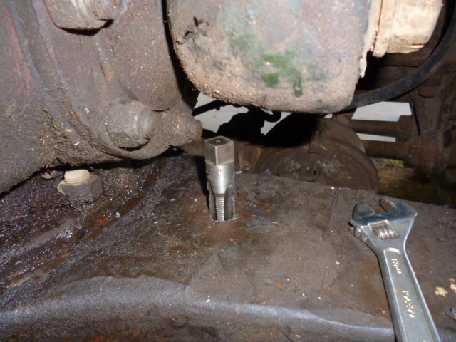
Used a die grinder, small cold chisel, magnet (so the bits fell up, not down) to get the breather remains out, re-tapped the thread in the housing which is 3/8" pipe. An easy-out wouldn't budge it at all. They are a very limited-use tool from my experience. Replaced the breather.
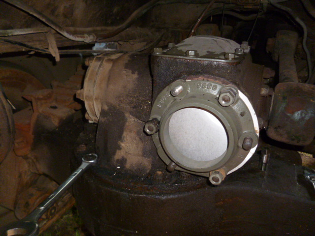
The other wet area was around the diff housing bolts. There were all loose, even finger tight for a couple. So re-tightened them. Easier said than done as there is not a lot of room between the diffs to swing a spanner with any power.
Another thing I did which seems to have worked very well is to glue a magnet, ex-computer hard drive, into the drain plug and level plug. Wow, did they pick up some fines!
Next is to start fitting the new bearings.
Have a nice day.
Sam.
I sealed up the diff openings and poured 16lts (4 US Gal.) of clean diesel into it, selected 6wd, and drive around the paddocks on the front diff for 1/2hr. Then returned to the workshop and drained the diesel to see what came out. Some gunk and, alarmingly, a lot of 'fines' that looked like rust. Before setting out to repeat the process, I noticed a wet axle housing in places. Hmm, no diff breather, broken off in the housing. You'd reckon I'd have checked that before now
Used a die grinder, small cold chisel, magnet (so the bits fell up, not down) to get the breather remains out, re-tapped the thread in the housing which is 3/8" pipe. An easy-out wouldn't budge it at all. They are a very limited-use tool from my experience. Replaced the breather.
The other wet area was around the diff housing bolts. There were all loose, even finger tight for a couple. So re-tightened them. Easier said than done as there is not a lot of room between the diffs to swing a spanner with any power.
Another thing I did which seems to have worked very well is to glue a magnet, ex-computer hard drive, into the drain plug and level plug. Wow, did they pick up some fines!
Next is to start fitting the new bearings.
Have a nice day.
Sam.
1942 Script GPW (Daily driver).
MB-T trailer.
Diamond T 969. ('The Glorifier')
Diamond T 969, rusty, complete, for sale.
Kenworth M1A1 Heavy Wrecker x 2.
M2A1 white HT. ('Clarrie')
Light Recovery Trailer (Ford?).
3ton GS (Blitz) Trailer.
150gal water tanker trailer.
Air compressor trailer, 100c.f.m.
MB-T trailer.
Diamond T 969. ('The Glorifier')
Diamond T 969, rusty, complete, for sale.
Kenworth M1A1 Heavy Wrecker x 2.
M2A1 white HT. ('Clarrie')
Light Recovery Trailer (Ford?).
3ton GS (Blitz) Trailer.
150gal water tanker trailer.
Air compressor trailer, 100c.f.m.
-
kw573
- G-Colonel
- Posts: 1235
- Joined: Mon Aug 11, 2008 10:48 pm
- Location: Near Bundaberg, Australia.
Re: M1 / M1A1 Heavy Wreckers and Accessories
Hi all,
Hmmm, things can change very quickly.
I thought I'd start cleaning up the top of the diff housing ready to fit the shaft and new bearings.
At one stage I leaned heavily on the crownwheel and it moved . . . sideways, a bit. So I gave it a good heave and it moves around like a boat on an anchor chain!! Clearly its' bearings are well and truly stuffed as well. There is nothing for it. The diff has to come out.
And get this . . in the two weeks it has been sitting, about 50ml of water had collected in the top part of the housing. And It has been very hot/dry weather.
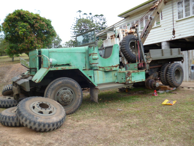
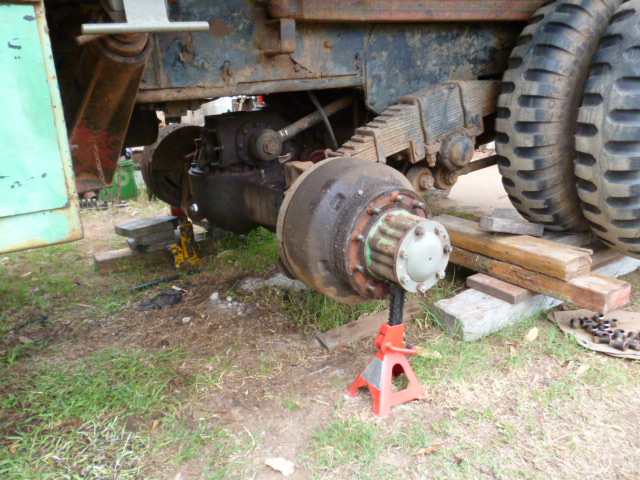
I jacked and blocked the rear wheels then removed the leading axle wheels and dropped the housing to get a lot more room above the housing. Looks do-able. Sort of. I gained 4" or so. It's a sorry looking case now.
That is enough for now.
Merry Christmas from Sam.
Hmmm, things can change very quickly.
I thought I'd start cleaning up the top of the diff housing ready to fit the shaft and new bearings.
At one stage I leaned heavily on the crownwheel and it moved . . . sideways, a bit. So I gave it a good heave and it moves around like a boat on an anchor chain!! Clearly its' bearings are well and truly stuffed as well. There is nothing for it. The diff has to come out.
And get this . . in the two weeks it has been sitting, about 50ml of water had collected in the top part of the housing. And It has been very hot/dry weather.
I jacked and blocked the rear wheels then removed the leading axle wheels and dropped the housing to get a lot more room above the housing. Looks do-able. Sort of. I gained 4" or so. It's a sorry looking case now.
That is enough for now.
Merry Christmas from Sam.
Who is online
Users browsing this forum: No registered users and 40 guests