Thanks for sharing what you have found on the differences between the AO42 and the AO42-2 & 3 engines, this is the first documentation that I have seen. Would be great if we could uncover the engineering notes for the mule engine development/conversion, but that's probably not going to happen (Phil B., here's a project for you!)
Would be really interested to hear more of your comments on the engine and on mules in general. Thanks again for sharing.
m274 ...
-
Chuck W.
- G-Lieutenant General

- Posts: 5820
- Joined: Wed Dec 18, 2002 11:00 am
- Location:
-
Auto Shop teacher
- G-Lieutenant Colonel

- Posts: 1188
- Joined: Sun Feb 02, 2014 10:46 pm
- Location:
Re: m274 ...
Chuck, with the low speeds that mules travel isn't horsepower a moot point as it takes torque to move a load. As you know that is one of the big advantages of diesels over gas engines as they produce more torque than a gas engine of the same size. Probably the reason for the head spacer to increase low end torque in mule applications, because a gen set engine must maintain a certain RPM to keep the AC close to 60 cycles.
Torque is much more important to a mule, and horsepower is more important to a generator.
Torque is much more important to a mule, and horsepower is more important to a generator.
Last edited by Auto Shop teacher on Wed Jul 29, 2015 4:32 pm, edited 2 times in total.
-
Chuck W.
- G-Lieutenant General
- Posts: 5820
- Joined: Wed Dec 18, 2002 11:00 am
- Location:
Re: m274 ...
You are correct, and it's not a big issue with me, I have had no problems using the gen set engine as a replacement for the mule. I've never really noticed any difference in the performance of the mule with either engine. I have run across a few folks who are convinced that the gen set engine will not perform in the mule and refuse to consider them as a viable option for a replacement engine. "it won't work!" I have always wondered exactly what was different. I have always thought that the goal by the military for selecting the AO42 engine was commonality with the same basic engine as used in other applications. Now it appears that there is enough differences between the engines to conclude that commonality was not a factor. All this being said, I still think the gen set engine is an excellent replacement option. Opinions?
-
Auto Shop teacher
- G-Lieutenant Colonel
- Posts: 1188
- Joined: Sun Feb 02, 2014 10:46 pm
- Location:
Re: m274 ...
Now the age old question is which mule was faster set up stock to specs, the early 4 cyl M274s, or the later 2 cyls? When they re-engine the 4s did they change anything in the running gear other than the block spacers to lift the deck?
While we are on this subject, I have heard stories of guys over in Vietnam bypassing the governor and getting their mules up to over 50 mph. Any truth to that story?
While we are on this subject, I have heard stories of guys over in Vietnam bypassing the governor and getting their mules up to over 50 mph. Any truth to that story?
-
muleman7
- G-First Lieutenant

- Posts: 646
- Joined: Mon May 14, 2007 5:36 pm
- Location: Georgia
- Contact:
Re: m274 ...
A guess
Let's say the top speed is 25 mph at 3600 RPM then 50 mph = 7200 RPM being a 1 to 1 ration in 3rd High. I have noticed that the 2 cyl will float valves around 5000 rpm. I will list documentation tonight.
TM 9-2320-246-34 Dec 67 pg 6-1 lists the A2,4 and 5 ratio [engine to drive pinion] as 2.440 to 1 and the A3 as 2.838 to 1
From my observations
The AO53 was set to max at 4000 rpm and the AO42 set to max at 3600
To maintain the same road speed the 2 gears in the Transmission were changed. The M274 had a 20 tooth mainshaft gear and the M274-A2 & A5 had a 22 tooth gear, the intermediate shaft also had to be changed. The TM listed below will show this for Fig 36 & 38
I have rebuilt M274-A2 & A5 transmissions using the M274 [A3] gear ratio for a 2 cyl application to get the lower ratio and I was not concerned about top end speed. Knowing that 10% reduction on 1st low is not as great as on 3rd high.
Also Items 2 & 8 fig 36 page 65 in TM 9-2320-246-34P Dec 1969 Bearing Retainer and Gear Retainer are different.
I know that the TM I listed only shows 1 set but I will post pics of the 2 sets. If my memory serves me the early set only allowed 1 Input Shaft Seal.
I will upload pics and list references this evening and review my older manuals to check the differences between the M274 and M274-A1 transmissions. I believe that the M274-A1 had external access to the 2nd-3rd Shift Rail spring and ball.
In Chuck's transmission overhaul the parts came out of a M274 transmission and into a M274-A2 transmission and the tooth count on the Main Shaft was 20. By the way it was an excellent pictorial and overhaul series.
Mules are my passion
www.m274armymules.com
www.m274armymules.com
-
Chuck W.
- G-Lieutenant General
- Posts: 5820
- Joined: Wed Dec 18, 2002 11:00 am
- Location:
Re: m274 ...
Is there enough adjustment on the governor high RPM stop to get 5000 RPM? Don't think I would want to be around it! I've seen numerous diesel engines come apart on our dyno over the years, some were very catastrophic, to say the least!
-
Auto Shop teacher
- G-Lieutenant Colonel
- Posts: 1188
- Joined: Sun Feb 02, 2014 10:46 pm
- Location:
Re: m274 ...
Thanks for the info Muleman, it would appear that about 35mph would be about all the 2 cyls could do without destroying the engine. While trashing gov property was not on a young solders mind when they are goofing off, I would think going even 35 with no suspension on such a short wheel base vehicle would be quite a ride. Add in the high center of gravity and 4 wheel steer it is no wonder that the A5 mules were only 2 wheel steer, more guys probably got hurt going too fast than in combat with them.
-
muleman7
- G-First Lieutenant
- Posts: 646
- Joined: Mon May 14, 2007 5:36 pm
- Location: Georgia
- Contact:
Re: m274 ...
I bypassed the Governor and using a manual RPM gauge off the crankshaft the AO42 engine would top out around 4400-4800. This is hard to observe with the engine screaming while trying to read the tach. I will try to post the documentation this weekend. I was busy today repairing my backhoe.
OK I have the information on the differences for the transmissions. I had to go back to an early TM 9-2320-213-34P Oct 1963 that covers the M274 and M274-A1. The transmission housings are listed separately along with the 2nd-3rd shift shafts. This tells me that the A1 had an external plug to access the 2nd-3rd poppet ball and spring. I will upload pics of each fig and list from the TM then I will upload pics of the actual gears and bearing retainers. I hope this will clearly describe the changes made and carried into the gears found in the A2 & A5. I do not have a source for engineering notes for the change nor why the change was made while still using the 4 cyl unless the AO53-1 was set to max at 3600 rpms. According to TM 9-7101-35 Apr 1958 the AO53 maxed at 4000 rpms.
Notice item 3 Input Shaft there are 2 listed
The M274 has 20 teeth and the M274-A1 has 22 teeth
I have more pics but I am only allowed 10 to be continued in another post.
OK I have the information on the differences for the transmissions. I had to go back to an early TM 9-2320-213-34P Oct 1963 that covers the M274 and M274-A1. The transmission housings are listed separately along with the 2nd-3rd shift shafts. This tells me that the A1 had an external plug to access the 2nd-3rd poppet ball and spring. I will upload pics of each fig and list from the TM then I will upload pics of the actual gears and bearing retainers. I hope this will clearly describe the changes made and carried into the gears found in the A2 & A5. I do not have a source for engineering notes for the change nor why the change was made while still using the 4 cyl unless the AO53-1 was set to max at 3600 rpms. According to TM 9-7101-35 Apr 1958 the AO53 maxed at 4000 rpms.
- TM 9-2320-213-34P Oct 1963
- TM 9-2320-213-34P Oct 1963.jpg (182.89 KiB) Viewed 8670 times
- Bearing Retainer fig 31 #s 3,5,10
- Brng Rtnr fig 31# 3,5,10.jpg (226.21 KiB) Viewed 8669 times
- Bearing Retainer List
- Brng Rtnr List.jpg (236.32 KiB) Viewed 8669 times
- Bearing Retainer Pics 1
- Bearing Retainer.jpg (235.65 KiB) Viewed 8668 times
- Bearing Retainer Pics 2
- Bearing Retainer 2.jpg (163.9 KiB) Viewed 8667 times
- Bearing Retainer M274-A1 Pic
- Bearing Retainer 1.jpg (232.97 KiB) Viewed 8669 times
- Main Shaft fig 34 item# 19
- Main Shaft fig 34 item# 19.jpg (168.75 KiB) Viewed 8669 times
- Main Shaft List
- Main Shaft List.jpg (202.09 KiB) Viewed 8669 times
- Main Shaft Pic
- Main Shaft.jpg (231.66 KiB) Viewed 8667 times
I have more pics but I am only allowed 10 to be continued in another post.
Mules are my passion
www.m274armymules.com
www.m274armymules.com
-
muleman7
- G-First Lieutenant
- Posts: 646
- Joined: Mon May 14, 2007 5:36 pm
- Location: Georgia
- Contact:
Re: m274 ...
Continued
The M274 has 36 teeth and the M274-A1 has 34 teeth
I have not found the #10 the Outer Bearing Retainer or the 2 different Input shafts. I am guessing that the only difference is the surface area for the seal or seals. The M274 used 1 seal and the M274-A1 used 2. the tooth count has to be the same since there is only 1 Countercluster Shaft listed for the transmissions.
I will post pictures when they are found.
- Intermediate Shaft fig 36 item# 9
- Intmediate Shaft fig 36 item#9.jpg (181.44 KiB) Viewed 8668 times
- Intermediate Shaft List
- Intermediate Shaft List.jpg (174.83 KiB) Viewed 8669 times
- Intermediate Gears
- Intermediate Gear.jpg (220.28 KiB) Viewed 8668 times
I have not found the #10 the Outer Bearing Retainer or the 2 different Input shafts. I am guessing that the only difference is the surface area for the seal or seals. The M274 used 1 seal and the M274-A1 used 2. the tooth count has to be the same since there is only 1 Countercluster Shaft listed for the transmissions.
I will post pictures when they are found.
Mules are my passion
www.m274armymules.com
www.m274armymules.com
-
Auto Shop teacher
- G-Lieutenant Colonel
- Posts: 1188
- Joined: Sun Feb 02, 2014 10:46 pm
- Location:
Re: m274 ...
WOW! What a LOT of information, I printed this up and will use this for reference when I go through a couple of my transmissions. Thanks!
-
muleman7
- G-First Lieutenant
- Posts: 646
- Joined: Mon May 14, 2007 5:36 pm
- Location: Georgia
- Contact:
Re: m274 ...
Continuation on the Differences between the M274 and the M274-A1 Transmissions.
I have posted all Pics on the G503 Photo Album under muleman7
Please check my other posting for TM references.
I dug through my parts and I think I have found the parts that are unique to the M274 and m274-A1 transmissions. they are the Input Shaft, Bearing Retainer, Bearing Retainer Main Shaft, Main Shaft, Intermediate Shaft and the 2nd 3rd Shift Shaft. I believe the remaining transmission internal parts are the same. Also the Transmissions and Cover Assemblies plus the Gasket and Seal Sets are different.
I will post pics and explanations for the Input Shafts and the Bearing Retainer Main Shaft [Input Shaft]
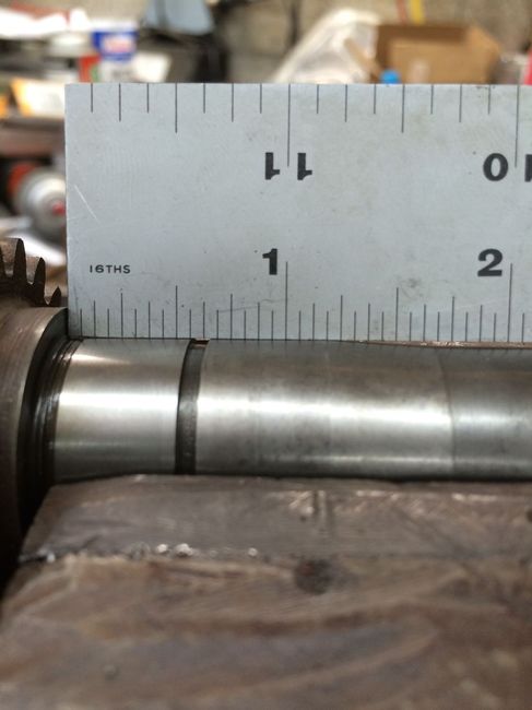
M274
Input Shaft you will notice that the Seal Area stops at 1-3/16 inch then tapers down there is a Seal mark at 27/64 [between 13/16 and 7/8].
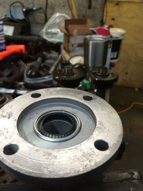
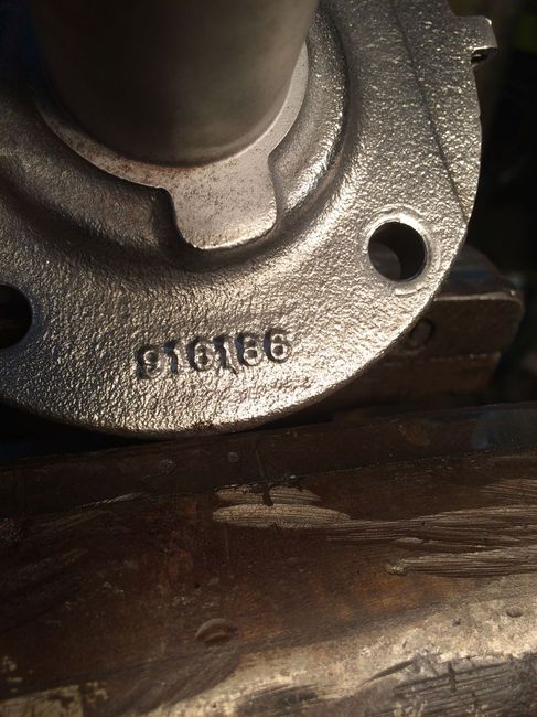
The Bearing Retainer Main Shaft [Input Shaft] has a deeper recess and has 1 Seal and the number cast into it is 918[6]186 to the best of my reading. This number does not correspond to previous post fig 31 Item 10 with Ord # 7760063??????????.
Maybe someone has other manuals that will explain this.
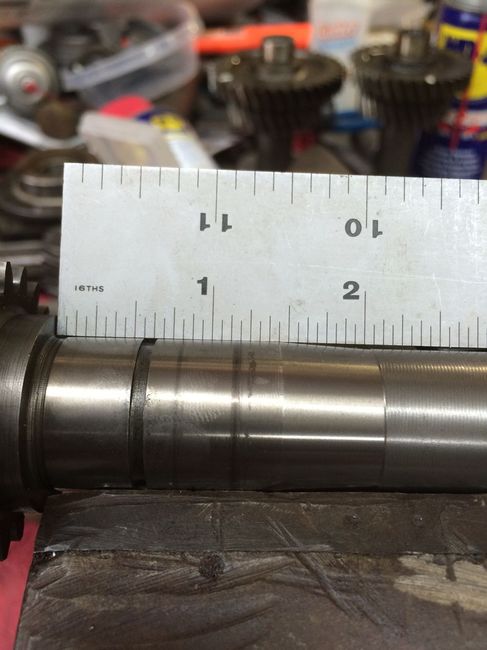
M274-A1
Input Shaft you will notice the the Seal Area stops at 1-7/16 inch then tapers down. You can also see where the 2 seals left marks.
The Bearing Retainer Main Shaft [Input Shaft] has a shallower recess and has 2 Seals and the number cast into it is 927181 to the best of my reading and corresponds to the Ord # in the previous post fig 31 Item 10.
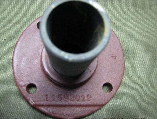
TM 9-2320-246-34P Dec 1968 Lists:
Bearing Retainer FSN 2520-588-0006 Ord# 7760062
Retainer Gear Transmission main drive gear [all models] FSN 2520.996-7218 Ord# 11592019 = see pic. The All Models does not equate since the M274 Bearing Retainer has a taller shoulder and will not allow the parts to seal using 1 gasket and the 2nd seal may not contact the seal area on the M274 Input Shaft. With out engineering notes it will be difficult to resolve the later manual references.
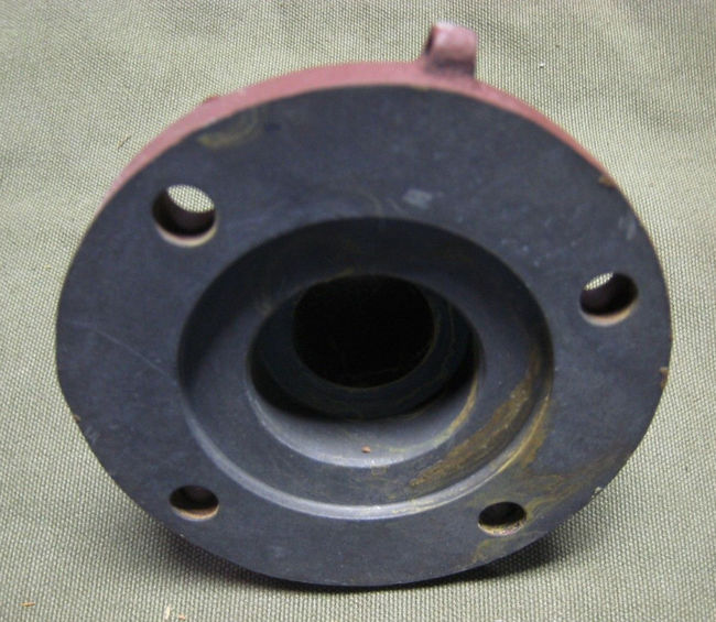
M274
M274 Input Shaft
M274 Bearing Retainer Main Shaft 1 Seal
M274 bearing Retainer #916186
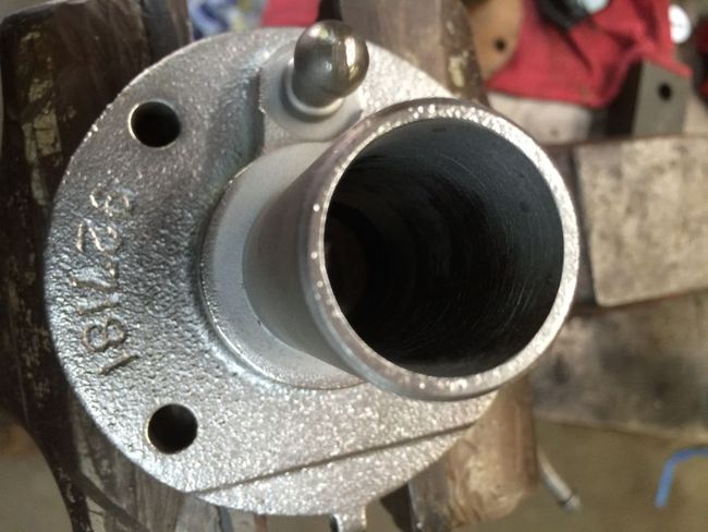
M274-A1
M274-A1 Input shaft
M274-A1 Bearing Retainer Input Shaft 2 seals
M274-A1 Bearing Retainer Input Shaft #927181
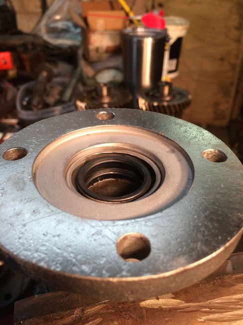
M274-A2, A5
M274-A5 Bearing Retainer Main Shaft notice the shallow recess and you can install 2 seals
M274-A5 Bearing Retainer Main Shaft #11592019
I have posted all Pics on the G503 Photo Album under muleman7
Please check my other posting for TM references.
I dug through my parts and I think I have found the parts that are unique to the M274 and m274-A1 transmissions. they are the Input Shaft, Bearing Retainer, Bearing Retainer Main Shaft, Main Shaft, Intermediate Shaft and the 2nd 3rd Shift Shaft. I believe the remaining transmission internal parts are the same. Also the Transmissions and Cover Assemblies plus the Gasket and Seal Sets are different.
I will post pics and explanations for the Input Shafts and the Bearing Retainer Main Shaft [Input Shaft]
M274
Input Shaft you will notice that the Seal Area stops at 1-3/16 inch then tapers down there is a Seal mark at 27/64 [between 13/16 and 7/8].
The Bearing Retainer Main Shaft [Input Shaft] has a deeper recess and has 1 Seal and the number cast into it is 918[6]186 to the best of my reading. This number does not correspond to previous post fig 31 Item 10 with Ord # 7760063??????????.
Maybe someone has other manuals that will explain this.
M274-A1
Input Shaft you will notice the the Seal Area stops at 1-7/16 inch then tapers down. You can also see where the 2 seals left marks.
The Bearing Retainer Main Shaft [Input Shaft] has a shallower recess and has 2 Seals and the number cast into it is 927181 to the best of my reading and corresponds to the Ord # in the previous post fig 31 Item 10.
TM 9-2320-246-34P Dec 1968 Lists:
Bearing Retainer FSN 2520-588-0006 Ord# 7760062
Retainer Gear Transmission main drive gear [all models] FSN 2520.996-7218 Ord# 11592019 = see pic. The All Models does not equate since the M274 Bearing Retainer has a taller shoulder and will not allow the parts to seal using 1 gasket and the 2nd seal may not contact the seal area on the M274 Input Shaft. With out engineering notes it will be difficult to resolve the later manual references.
M274
M274 Input Shaft
M274 Bearing Retainer Main Shaft 1 Seal
M274 bearing Retainer #916186
M274-A1
M274-A1 Input shaft
M274-A1 Bearing Retainer Input Shaft 2 seals
M274-A1 Bearing Retainer Input Shaft #927181
M274-A2, A5
M274-A5 Bearing Retainer Main Shaft notice the shallow recess and you can install 2 seals
M274-A5 Bearing Retainer Main Shaft #11592019
Last edited by muleman7 on Fri Aug 28, 2015 2:59 am, edited 3 times in total.
Mules are my passion
www.m274armymules.com
www.m274armymules.com
Who is online
Users browsing this forum: No registered users and 35 guests